Back-Engineered Methernitha - by Paul E Potter
То, что группа Швейцарцев Метерниты, Testatika машина(механизм), как думают, является основанной на Wimshurst электростатическом генераторе, является только редким приближением правды - большого множества электростатических машин(механизмов) влияния, развитых вокруг 1900-ых, это более близко следует за системой "разделение нагрузки(обвинения) и собрание" используемый 1898 Pidgeon машина(механизм) [note 1] для ее электрической схемы.
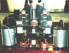
Его 50-per-disc стальные решетки или ' gitter-решетки явно уникальны к Methernitha (см. рис. 1) но в принципе следуют за предыдущим исследованием и патентами для рифленых секторов, которые были найдены, чтобы быть более эффективными крепежными элементами нагрузки(обвинения) [note 2] чем плоские, и от подобного примера в более современных временах алюминиевых стержней, простирающихся из подобного колеса говорит от ступицы изолирования относительно perspex [note 3].
Другая уникальная функция этих перфорированных решеток, приложенных к дискам - то, как они стимулируют нагрузку(обвинение) от вращающихся дисков на специальные колодки сбора, или 'tasten' ключи антенн (которые также перфорированы - чтобы более с готовностью приобрести(подобрать) нагрузку(обвинение)); Поскольку в Wimshurst Вы имели благоприятные щетки или рельсы острых пунктов(точек), которые фактически коснулись дисков или были помещены очень близко к ним, но в Methernitha, нагрузка(обвинение) должна быть сделана к пересечению параллельным воздушным промежутком к колодкам и для этой цели, металлические gitter-решетки так разработаны(предназначены), чтобы создать миниатюрные потоки вихри обвиненного(заряженного) воздуха, которые циркулируют в и из поверхностных обвинений перфорированного металла,И более легко дрожат из к собирающимся колодкам. Этот процесс категоризирован как ПЕРЕМЕННАЯ ЕМКОСТЬ электростатическое поколение.
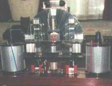
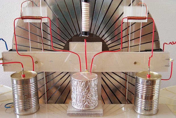
Осторожное примечание должно быть сделано того, как Methernitha использует его в основном Pidgeon установку в отношении его стержней нейтрализации (которые уравнивают и стабилизируют противоположные обвинения - видят рис. 2), и как обвинения поднимаются от одной области и накоплены в других, так, чтобы полярности нагрузки (обвинения) были распределены правильно определенным областям на обоих дисках [note 4].
И хотя имелись некоторые причудливые рекламации, или дезинформация, что это использует все виды радиоактивных материалов, чтобы достичь ее pulsed продукции(выпуска), я наиболее настоятельно верю, что вспомогательный электромагнитный кругооборот, что обертки самостоятельно вокруг вращающихся дисков, изображают простой электронный подход; afterall, кто использовал бы радий радиоактивная эмиссия рядом с leyden конденсаторами фляги! Действительно, больше Вы изучаете некоторые элементы его конструкции, больше они указывают на три главных эры развития электроники, 1900-ых, 1920-ых и 1950/60's. Подлинный Methernitha был разработан(предназначен) и развит пуристами, кто полагали, что они обнаружили предварительно неизвестное электронное явление, но они хотели держать целостность(честность) к раннему руководству днями Pidgeon, Wimshurst и Holtz электростатических машин; они не использовали бы такие современные устройства как транзисторы или IC чипы (more's жалость) - но они используют некоторую довольно необыкновенную электронную разработку в их кругообороте [note 5] .
Очевидно, электроника находится в двух частях; один - электростатический генератор и его специфические технологии того, как направить, какой нагрузку(обвинение), где, и два - самый уникальный вспомогательный электромагнитный кругооборот индуктивности, емкостей и исправления, которое мобилизует это 'статическое' электричество. Чтобы понимать, как они конвертируют(преобразовывают) статическую энергию в силу electromotive, Вы преуспели бы, чтобы возвратиться к самым ранним годам радио. От страниц радио искры зажигания Вы скоро оцениваете только, как важные кругообороты колебания и их ректификаторы клапана были, и кроме того, как трудный это, оказалось, проектировало их. Поскольку, хотя передатчики радио и приемники с 1900-ых используемые резонирующие кругообороты, их колебания управлялись искрами зажигания между двумя контактами и, конечно, они были относительно неэффективны. Только когда 1920-ые первые колебания электрического тока станут заметным , управлял явлением, когда кто - то соединил клапан ректификатора, конденсатор, и резистор вместе [note 6] . Ранний(рано) 1920-ых также видел лучшую эру экспериментирования и изобретения для новых устройств, которые направили статическую энергию в годную к употреблению электромагнитную энергию; Именно в 1921 патенте мы видим, что Немецкий физик Херманн Плаусон описывает в большой детали его методы конвертировать(преобразовать) статическую мощность(энергию), не только от вращательных машин(механизмов) влияния но также и от воздушных шаров, собирающих атмосферное электричество в небе; и, используя thermionic ректификаторы, leyden конденсаторы фляги и спирали катушки индуктивности он предложил сеть с свободной энергией, которая была к мощности(энергии) вся Германия [note 7] ! Thermionic клапан ректификатора объявил новую эру для радио и физики высокого напряжения, и поскольку это было тогда подвергнуто такому широкому множеству экспериментов и модификаций, чтобы улучшить его эффективность, так что это проложило путь к всем видам новых направлений в электронике. Действительно, с таким техническим каталогом подобий с тем, что мы видим на доступных фотографиях Testatika, это может быть принято без сомнения, что горизонтальная стеклянная труба(зонд), которая сидит на вершине Methernitha машин(механизмов) - точно, что вакуум отечественного производства thermionic исправление клапана напомнило бы; С его внутренней пластиной отверстия анода, окруженной намотанной медной сеткой, питаемой пылающим (нагретым) проводом катода управление горизонтально поперек его центра и удивленный двумя черными частями конца, которые являются слишком большими и выпуклыми, чтобы быть простыми торцевыми заглушками и должно конечно быть черные резиновые вакуумные изоляции, чтобы изолировать стеклянную трубу(зонд) и провода входа / продукции [note 8].
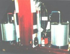
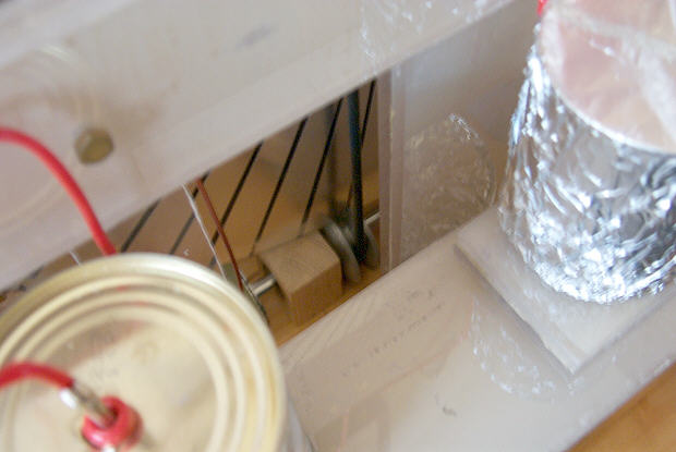
С таким ректификатором, некоторыми катушками зажигания, и некоторыми leyden конденсаторами фляги Вы имеете кругооборот, который колеблется, и это - то, что должно случиться с Methernitha, электромагнитный кругооборот должен колебаться для этого, чтобы работать, и затем колебания должны быть исправлены (или даже модулироваться) так, чтобы заканчивающиеся пульс единственного полюса могли быть channeled через большие канистры, которые являются в основном трансформаторами с высокой эффективностью, И outputted как уменьшенное напряжение более высокий поток DC пульс (см. рис. 3).
Точные компоненты имели обыкновение колебаться, первичный колеблющийся кругооборот, я верю, не быть замечен на любой из доступных фотографий, но имеются различные намеки для их приблизительного местонахождения на машине(механизме). Во-первых, согласно электронному проекту должен иметься конденсатор и конфигурация спирали в близкой близости к ректификатору. Хорошо, от картины "3KWREAR" Может быть замечен две длинных трубы(зонда) стойки, которые, согласно тем, кто видели их непосредственно, включают по спирали превращенную(направленную) алюминиевую полосу (который указывает, что они - заслонки [note 9] ) Внутри стеклянной трубы(зонда), внутри того же самого вида внешнего ограждения, которое большие канистры имеют (который указывает, они - электростатические щиты), внутри все же другой стеклянной трубы(зонда), и закончены наверху с медным шатуном, который делает прямоугольный поворот и пропускает в сторону башни - но только двумя треть высота башни. Эти две сборки должны формировать связь к ректификатору, потому что ректификатор имеет наверху башню, так, почему эти electrostatically чувствительные трубы(зонды) не расширяют(продлевают) полностью до это? Снова, от фотографий тыла и фронта Methernithas имеется провод, который выходит из стены стороны башни в, приблизительно 4 дюйма выше медных зажимов стойки и этого провода тогда проходят через короткую черную трубу(зонд) и на к клапану ректификатора. Это, конечно, случилось бы с обеих сторон башни, позволяя связи к обоим концам ректификатора. Но почему имейте промежуток этот 4 дюйма связей наверху башни? Кое-что помещено внутри вершины башни в этом промежуточном месте, которое является очень необходимым для кругооборота, и я думаю, что это должно быть местоположение конфигурации конденсатора / катушки индуктивности, чтобы колебаться кругооборот. Этот ( рис. 4) - то, как я видел бы внутреннюю часть вершины башен [note 10] .
Я видел некоторых из патентованных изобретений, которые вращают диски - используя магниты (то есть постоянный магнит Х.Росенберга возбудил вращательную машину(механизм), США патентуют 3,411,027), и, используя надписанные metalised диски (США патентуют 3,239,705 например), но просто не имеется достаточно комнаты(места) для них, чтобы быть расположенным в Methernitha установке дисков - также, Вы не хотите сталкиваться с ES областями(полями) что почтовый индекс вокруг автоматически возобновляемых дисков: От reports Тех, кто видели < I> маленькие машины(механизмы) работа это, кажется(появляется), что их диски вращались маленькими DC электродвигателями после того, как они были начатые рукой, некоторые заново ранят с более тонким проводом (чтобы возможно увеличить их torque) и включенный непосредственно от дисков Произведенное электричество - но я также видел, как два диска могут продолжать вращаться просто осторожным размещением изогнутых электродов [note 11] , который действовал бы по обвинениям на диски - подобно 3kw Testatica Distatica генераторы.
После пролистывания многих ранних счетов электростатических вращательных машин(механизмов), и некоторых из более современных, Вы не можете не быть озадаченными невероятно низкой вращательной скоростью Метерниты только 60 оборота в минуту (и в 1999 сообщении инженеров как низко as:15 оборот в минуту!). Большинство других ранних экспериментаторов хвасталось до 3000 оборота в минуту. J.G.Trump в его работе на поколении высоких напряжений в месте [note 12] прял его вращательную машину(механизм) в 10,000 обороте в минуту (чтобы произвести 433 Ватта в 24 KV не меньше). Одна причина для этой низкой скорости могла бы быть, чтобы делать с близкой близостью из 50 lamellas (gitter-решетки) на дисках в их внутренние концы, они - очень близко друг к другу, я думаю слишком близко. Воздух, обычно изолятор, сломает и проводит в пределах 25-35 KV (это число(фигура) было справедливо(довольно) постоянно от "день один" электростатических экспериментов машины(механизма) прямо через к существующему дню - потому что воздух имеет силу области(поля) поломки 3x10 < ГЛОТОК > 6 < / глоток > вт / метр) и короткие замыкания кругооборот. Я чувствую, что, потому что этот проект решеток склонный к короткому - circuiting в высоких напряжениях, Methernitha люди ограничили их вращательную скорость, чтобы гарантировать низкое рабочее напряжение - того, что я был бы guesstimate, чтобы быть только 12 к 24KV.
Но, это - отходы дополнительного потенциала? Не necessarily:For я не думаю, что главная продукция(выпуск) мощности(энергии) прибывает исключительно от того, что два вращающихся мятежника диска снабжают.
Имеется, я верю, что гораздо более важная мощность(энергия) generator:the электронный каскадный генератор , и Methernitha имеет два из них, держался внутри двух магнитов подковы, и обеспечение кругооборотов к магнитам сделано, чтобы колебаться в правильной частоте в достаточно высоком напряжении, тогда эти metalised-perspex слоистые блоки могут enmass НАМНОГО БОЛЬШЕЕ КОЛИЧЕСТВО ЭЛЕКТРИЧЕСТВА ЧЕМ ТО, ЧТО ПОМЕЩЕНО В НИХ.
Это, возможно, является предварительно неизвестным электронным явлением, которое Methernitha группа так рьяно пробовал защищать против недобросовестных предпринимателей. Но я говорил бы, что эта обильная поставка свободной энергии уже известна к миру - это не с готовностью доступно - и его принципы полностью не поняты, пока еще, но это известно относительно.
Поскольку описания говорят (относительно Testatika Website), между ногами(опорами) магнита подковы - четыре блока прозрачных ' plexiglass, напечатают материал, чередуемый с медными и алюминиевыми пластинами (который может или не может быть перфорирован), в последовательности c-p-a-c-p-a-c-p-a-c-p-a (также см. рис. 6). И согласно Эксперимент Линдена где Пауль Бауманн стимулирует резонанс приблизительно 80-140 MHz в намотанной подкове и затем, имеет блок "алюминиевая медь изолятора" перемещенный между ногами(опорами) подковы, напряжение могло быть снижено(удалено) пластины блока, который измерил 700 вт (DC возможно) [note 13] . Это невероятное явление никогда не копировалось любым ' внешний исследователь ', и как считают, основание, которым Methernitha машина(механизм) могла быть понята, как работать [ключ, возможно, к этому, принципиальный Эксперимент может с переменной емкостью и dielectric-absorpsion].
Но что, я слышу, что Вы говорите, является электронным каскадом ... Хорошо, это было только случайно, очень недавно, что я, случился, слушал звуковую ленту доктором Фланаганом относительно кристаллической воды; когда я переключил ленту после конца стороны, один доктор Фланаган тогда начал говорить относительно электронной конфигурации, которая применила высокую частоту, высокое напряжение, чередующее область(поле) поперек изолятора - который создавал то, что он назвал электронным каскадным эффектом - Да, я думал, имеется ответ на Methernitha Машину.
Электронный каскад или эффект лавины - то, где воздушные молекулы ускорены на устройство в такой высокой скорости, что они сталкиваются с другими молекулами и атомами в воздухе, чтобы освободить новые электроны, которые в свою очередь также сталкиваются и освобождают даже большее количество ' свободные электроны от других воздушных молекул (см. рис. 5), все из которых станут ускоренный электрическое поле, и лавина электронный умножение прогрессирует повсюду целой непосредственной(немедленной) окружающей среды [note 14]. Это - реакция цепи, и полностью безопасная, это случается более свирепым способом в забастовках молнии, и - естественное явление. И, как в этом случае, окружающая среда фактически становится частью кругооборота [note 15] , потому что процесс фактически negatively-ионизирует воздух, окружающий Methernitha машины(механизмы), и именно поэтому те, кто были около этих генераторов, когда работа говорит, что воздух вокруг относительно них прохладен и нов(свежий) [note 16] .
Ввиду факта, что это является, проектировщики хотели проветривать изолированный провод (который может или не может быть bifilar) вокруг металла подковы, вероятным, что подковы используются для некоторой формы индукции [note 17] , iT был бы также очень возможен тянуть(рисовать) непосредственно от этой части кругооборота дополнительный электрический ток, произведенный от электронных каскадных блоков, с подходящими связями, которые могли бы шаг вниз в деревянную основу (где полагается, что дополнительное иерархическое представление перфорированных металлических пластин и пластин изолирования - составление большого конденсатора хранения высокого напряжения - расположено). Эта мощность(энергия) могла тогда быть разряжена как pulsed продукция(выпуск) высокого wattage, особенно, если заключительная часть продукции(выпуска) электронного кругооборота - configured как Пульс, формирующий Сеть многократных секций катушки индуктивности / конденсаторные комбинации [note 18] .
Две больших канистры в стороне, больших конденсаторах, вероятно не высоко технические (см. рис. 7), как только фундаментальная формула была решена относительно всех моделей Testatika генератора, будет следовать за подобным процессом конструкции. Письменные описания немного противоречащие, но они, кажется, предлагают центральный стержень входа, или трубу(зонд), соединяющуюся на дне канистр к стеку связанных спиралей блина, которые являются раной вторичный - вне первичного - внутреннего, приспособленного вокруг ядра 6 полых кольцевых по пончику магнитов, сложенных таким способом с пластиковыми прокладками, чтобы позволить воздушные промежутки между ними, И затем наконец продукция(выпуск) каждого может быть связь от высшей спирали secondaries спиралей блина к медному кольцу вокруг центра черной пластиковой высшей крышки - и от фотографий может быть замечен большой провод диаметра или труба(зонд)[note 19] Соединение, что выход полярности к медному кольцу высшей крышки через медный зажим винта. Я говорил бы, что кольцевые магниты (anistropic феррита возможно) - gapped таким образом, чтобы предотвратить магнитные области(поля) потока первичных выборов блина соединяющийся компания как одна растягивающаяся область(поле), потому что это было бы более выгодно, и более безопасное, иметь магнитный поток каждого отдельного блина сокращают это - собственная смежная вторичная обмотка, И делите вторичное выходное напряжение в меньшие количества потенциала, таким образом зависящего меньше на сложных процедурах изолирования, которые сопровождают высокое напряжение единственный(отдельный) первичный / единственные(отдельные) вторичные трансформаторы.
Использование алюминиевого отверстия и твердого медного защитного покрытия обычно используется в электронной конструкции; внешний алюминиевый цилиндр отверстия использовался бы, чтобы оградить беспризорные электростатические обвинения, и твердый медный цилиндр должен оградить большое количество беспризорных электромагнитных областей(полей), произведенных процессом преобразования от высокого напряжения / низкий поток, чтобы понизить поток напряжения / более высокого [note 20]. Очевидно они не хотят полевое загрязнение, имеющее место между чувствительным электростатическим генератором и трансформаторами.
В пределах этих двух внешних ограждающих - цилиндров - ' конденсаторы сетки который, согласно 1999 сообщению 30 инженерами, может быть целых 20 слоев перфорированного листа (возможно как концентрические цилиндры) - который я указал (в рис. 7 например) как электрически соединились МЕЖДУ каждой отдельной обмоткой ротора - в моде старого открытия с ранних дней беспроволочной телеграфии и основанный на ' подрывная спираль разрядки ' изобретенный Nikola Tesla, Это такой конденсатор, связанный в центре вторичной обмотки собирает(забирает) максимальное количество напряжения, созданного этим вторичный. Эта конфигурация одного конденсатора внутри другой внутренней части другой и т.д и т.д, имеет поразительное подобие расположению пульса, формирующего сеть [see, обращают внимание 18] .
В красном зашитый может трансформатор - зашитым к продукции(выпуску), отрицательной, и трансформатор синего зашитого can's зашит к продукции(выпуску) положительная полярность. Специальное примечание должно быть сделано подобного расположения для разделенного первичным / обмотками ротора, изобретенными Фургоном Graaff в его ' Высокое напряжение Электромагнитным Аппаратом Акселератора Обвиняло - частицы Наличием Изолирующего Магнитного Ядра ' [note 21] относительно магнитных промежутков нежелания.
Пока сказалось, что ясный perspex диск был обозначен диск 'облака', и (тыловой) темный диск диск 'основания'('земли') я буду думать, что это касается различных типов acrylics или пластмасс, которые могли бы стать заряженными к различным полярностям, как в triboelectric ряде, где frictional зарядка различных пластмасс - и затем обеспечение им близко друг к другу, могли бы причинять пожертвование или принятие от один до другой; Я думал бы от вышеупомянутого, что облако представляет дарителя (положительный заряд), и то основание(земля) должно означать акцепторный (отрицательный заряд). Любой пробовал комбинацию teflon диска (чрезвычайно отрицательный заряд) со стеклянным диском (высоко положительный заряд)?
Или диски doped с paramagnetic частицами возможно [note 22] ?
Testatika проект, основанный на Pidgeon/Wimshurst машине(механизме) - конечно только один тип электростатического генератора, чтобы строить эту систему вокруг. Начиная с раннего(рано) 1900-ых такие генераторы мощности(энергии) прибыли длинный путь в сложность(искушенность) - и в продукцию(выпуск) мощности(энергии) - недавно развитая продукция(выпуск) машин(механизмов) 300,000 вт, которые могут тогда быть преобразованы и использоваться [note 23] .
If you would like to comment on any of the items on this site please e-mail Freeelectric.
Back-Engineered Methernitha _ by Paul E Potter
That the Swiss Methernitha group's Testatika machine is thought to be based on a Wimshurst electrostatic generator, is only a sparse approximation of the truth _ of the great multitude of electrostatic influence machines developed around the 1900's it more closely follows the charge-separation-and-collection system used by the 1898 Pidgeon machine [note 1] for its electrical circuit.
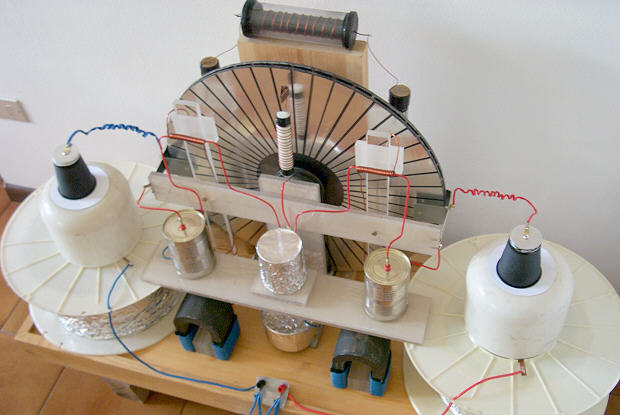
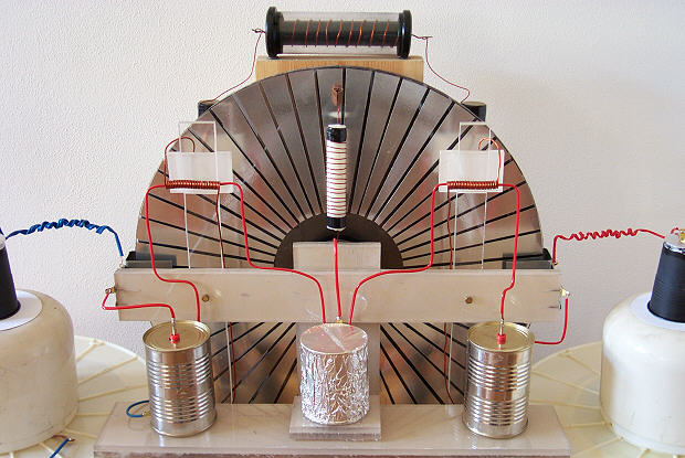
Its 50-per-disc steel grilles or 'gitter-grilles' are plainly unique to the Methernitha (see fig.1) but in principle follow on from previous research and patents for corrugated sectors which were found to be more efficient charge carriers [note 2] than flat ones, and from a similar example in more recent times of aluminium rods extending out like wheel spokes from an insulating hub of perspex [note 3].
Another unique function of these perforated grilles attached to the discs is how they induce charge from the rotating discs onto the special collecting pads, or 'tasten' antennae keys (which are also perforated _ so as to more readily pick up charge); for in a Wimshurst you had conductive brushes or rails of sharp points which actually touched the discs or were placed very close to them, but in the Methernitha the charge has to be made to traverse a parallel air-gap to the pads and for this purpose the metal gitter-grilles are so designed to create miniature eddy-currents of charged air which circulate in and out of the perforated metal's surface charges, and are more easily bounced out to the collecting pads. This process is categorised as VARIABLE CAPACITANCE electrostatic generation.
Careful note needs to be made of how the Methernitha uses its basically Pidgeon setup with regard to its neutralising rods (that equalise and stabilise the opposite charges _ see fig.2), and how charges are picked up from one area and accumulated at others, so that the polarities of charge are distributed correctly to specific areas on both discs [note 4].
And although there have been some fanciful claims, or misinformation, that it uses all sorts of radioactive materials to achieve its pulsed output I most strongly believe that the auxiliary electromagnetic circuit, that wraps itself around the rotating discs, portrays a simple electronic approach; afterall, who would use radium radioactive emission alongside leyden jar capacitors ! Indeed, the more you look into certain elements of its construction the more they point to three main eras of electronics development, the 1900's, the 1920's and the 1950/60's. The authentic Methernitha was designed and developed by purists who believed they had discovered a previously unknown electronic phenomenon, but they wanted to keep an integrity to the early pioneering days of the Pidgeon, Wimshurst and Holtz electrostatic machinery; they would not use such modern devices as transistors or IC chips (more's the pity) _ but they do use some pretty uncommon electronic engineering in their circuit [note 5].
Obviously, the electronics are in two parts; one _ the electrostatic generator and its particular technologies of how to direct what charge where, and two _ the very unique auxiliary electromagnetic circuit of inductances, capacitances and rectification that mobilises that 'static' electricity. To understand how they convert static energy into an electromotive force you would do well to go back to the earliest years of radio. From the pages of spark radio you soon appreciate just how important oscillation circuits and their valve rectifiers were, and moreover, how difficult it proved to engineer them. For although radio transmitters and receivers from the 1900's used resonating circuits their oscillations were controlled by sparks between two contacts and, of course, they were relatively inefficient. Not until the 1920's did the first electric current oscillations become an observable controlled phenomenon when someone coupled a rectifier valve, a capacitor, and a resistor together [note 6]. The early 1920's also saw the best era of experimentation and invention for novel devices that turned static energy into useable electromagnetic energy; it was in a 1921 patent that we see a German physicist Hermann Plauson describe in great detail his methods to convert static power, not only from rotary influence machines but also from balloons collecting atmospheric electricity up in the sky; and by using thermionic rectifiers, leyden jar capacitors and inductor coils he proposed a free-energy network that was to power the whole of Germany [note 7] ! The thermionic rectifier valve heralded a new era for radio and high voltage physics, and as it was then subjected to such a broad array of experiments and modifications to improve its efficiency so it paved the way for all sorts of new avenues in electronics. Indeed, with such a technical catalogue of similarities with what we see in the available photographs of Testatika it can be assumed without doubt that the horizontal glass tube which sits on top of the Methernitha machines is exactly what a home-made vacuum thermionic rectifying valve would look like; with its internal anode mesh-plate, surrounded by a coiled copper grid, fed by a glowing (heated) cathode wire running horizontally across its centre and capped by two black end-pieces, which are too big and bulbous to be mere end-caps and must surely be black rubber vacuum seals to seal the glass tube and the input/output wires [note 8].
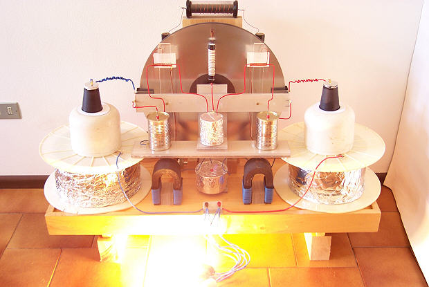
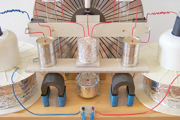
With such a rectifier, some induction coils, and some leyden jar capacitors you have a circuit that oscillates, and that's what has to happen with a Methernitha, the electromagnetic circuit has to oscillate for it to work, and then the oscillations have to be rectified (or even modulated) so that the resulting single-pole pulses can be channeled through the big cans, which are basically high-efficiency transformers, and outputted as reduced voltage higher current DC pulses (see fig.3).
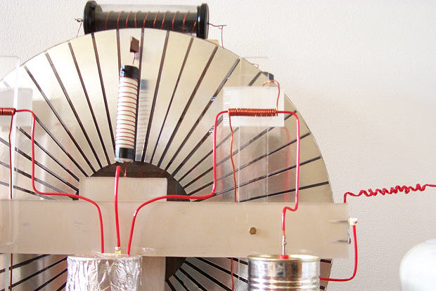
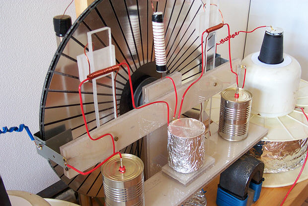
The precise components used to oscillate the primary oscillating circuit are, I believe, not to be seen in any of the available photographs, but there are various hints for their approximate whereabouts on the machine. Firstly, according to electronic design there should be a capacitor and coil configuration in close proximity to the rectifier. Well, from the picture "3KWREAR" can be seen the two long upright tubes which, according to those who have seen them first-hand, comprise a spirally turned aluminium strip (which indicates they are chokes [note 9]) inside a glass tube, inside the same sort of outer shielding that the big cans have (which indicates they are electrostatic shields), inside yet another glass tube, and are terminated at the top with a brass connecting rod which does a right-angled turn and passes into the side of the tower _ but only two-thirds up the height of the tower. These two assemblies must form a connection to the rectifier, because the rectifier is at the top of the tower, so why don't these electrostatically sensitive tubes extend all the way up to it ? Again, from the photographs of the rear and front of the Methernithas there is a wire that comes out of the tower's side wall at about 4 inches above the upright's brass terminals and this wire then passes through a short black tube and on to the rectifier valve. This, of course, would happen on both sides of the tower, enabling a connection to both ends of the rectifier. But why have this 4 inch gap of connections at the top of the tower ? Something is placed inside the top of the tower in this intermediate space which is very necessary to the circuit, and I think it must be the location of the capacitor/inductor configuration to oscillate the circuit. This (fig.4) is how I would see the inside of the top of the towers [note 10].
I've seen some of the patented inventions that rotate discs - by using magnets (ie H.Rosenberg's permanent magnet excited rotational machine, US patent 3,411,027), and by utilising inscribed metalised discs (US patent 3,239,705 for instance), but there simply isn't enough room for these to be located in the Methernitha disc setup _ also, you don't want to interfere with the ES fields that zip around the revolving discs: From the reports of those who have seen the small machines working it appears their discs were rotated by small DC electric motors after they were hand-started, some re-wound with thinner wire (to presumably increase their torque) and powered directly from the discs' generated electricity _ but I have also seen how two discs can continue to rotate simply by careful placement of curved electrodes [note 11] which would act on the charges on the discs _ like the 3kw Testatica Distatica generators.
After reading through the many early accounts of electrostatic rotary machines, and some of the more recent ones, you can't help but be puzzled by the Methernitha's incredibly low rotational speed of just 60 rpm (and in the 1999 engineers report as low as_15 rpm !). Most other early experimenters boasted up to 3000 rpm. J.G.Trump in his work on high voltage generation in space [note 12] spun his rotary machine at 10,000 rpm (to produce 433 Watts at 24 KV no less). One reason for this low speed might be to do with the close proximity of the 50 lamellas (gitter-grilles) on the discs at their inner ends, they are very close together, I think too close. Air, normally an insulator, breaks down and conducts at around 25-35 KV (this figure has been fairly constant from day-one of electrostatic machine experiments right through to the present day _ because air has a breakdown field strength of 3x10⁶ volts/metre) and short-circuits the circuit. I feel that because this design of grilles is prone to short-circuiting at high voltages the Methernitha people have limited their rotational speed so as to ensure a low operating voltage _ of what I'd guesstimate to be only 12 to 24KV.
But, is this a waste of extra potential ? Not necessarily_For I don't think that the main power output comes solely from what the two contra-rotating discs supply.
There is, I believe, a far more important power generator_the electron cascade generator, and the Methernitha has two of them, held inside the two horseshoe magnets, and providing the circuits to the magnets are made to oscillate at the right frequency at a high enough voltage then these metalised-perspex laminated blocks can enmass A MUCH LARGER AMOUNT OF ELECTRICITY THAN WHAT IS PUT INTO THEM.
This, perhaps, is the previously unknown electronic phenomenon that the Methernitha group have so zealously been trying to protect against unscrupulous entrepreneurs. But I would say that this copious supply of free energy is already known to the world - it is not readily available - and its principles are not fully understood, as yet, but it is known about.
As the descriptions say (on the Testatika website), between the horseshoe magnet legs are four blocks of transparent 'plexiglass' type material alternated with copper and aluminium plates (that may or may not be perforated), in the sequence c-p-a-c-p-a-c-p-a-c-p-a (also see fig.6). And according to the Linden Experiment, where Paul Baumann induces a resonance of about 80-140 MHz in a coiled horseshoe and then has an aluminium-insulator-copper block moved between the horseshoe legs, a voltage could be taken off the plates of the block which measured 700 volts (DC presumably) [note 13]. This incredible phenomenon has never been replicated by any 'outside researcher', and is said to be the basis by which the Methernitha machine could be understood how to work [the clue, possibly, to this Principle Experiment may be variable-capacitance and dielectric-absorpsion].
But what, I hear you say, is an electron cascade... Well, it was only by chance, very recently, that I happened to listen to an audio tape by a Dr. Flanagan about crystal water; when I switched the tape over after the end of side one Dr. Flanagan then began talking about an electronic configuration that applied a high frequency, high voltage alternating field across an insulator _ that created what he called an electron cascade effect _ Yes, I thought, here is the answer to the Methernitha Machine.
The electron cascade or avalanche effect is where air molecules are accelerated to the device at such a high velocity that they collide with other molecules and atoms in the air to liberate new electrons which in turn also collide and liberate even more 'free electrons' from other air molecules (see fig.5), all of which become accelerated by the electric field, and an avalanche of electron-multiplications progresses throughout the whole immediate environment [note 14]. It's a chain reaction, and an entirely safe one, it happens in a more ferocious way in lightning strikes, and is a natural phenomenon. And, as in this case, the environment actually becomes part of the circuit [note 15] because the process is actually negatively-ionising the air surrounding the Methernitha machines, and that is why those who have been near these generators when working say the air around about them is cool and fresh [note 16].
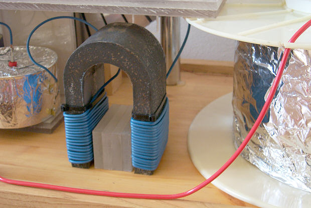
In view of the fact that it's designers have chosen to wind insulated wire (which may or may not be bifilar) around the horseshoe metal it is likely that the horseshoes are used for some form of induction [note 17], it would also be very possible to draw directly from this part of the circuit the extra electric current produced from the electron cascade blocks, with suitable connections that might lead downward into the wooden base (where it is believed that an alternate layering of perforated metal plates and insulating plates - making up a large high-voltage storage capacitor - is located). This power could then be discharged as a pulsed output of high wattage, especially if the final output part of the electronic circuit is configured as a Pulse Forming Network of multiple sections of inductor / capacitor combinations [note 18].
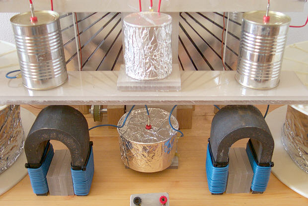
The two big cans at the side, the big capacitors, are probably not highly technical (see fig.7), once the fundamental formula has been decided upon all models of a Testatika generator would follow a similar construction process. The written descriptions are a little contradictory but they seem to suggest a central input rod, or tube, connecting at the bottom of the cans to a stack of inter-linked pancake coils, that are wound secondary-outside primary-inside, fitted around a core of 6 hollow donut-ring magnets stacked in such a way with plastic spacers as to allow air gaps between them, and then finally the output of each can is a connection from the top coil of the secondaries of the pancake coils to a brass ring around the centre of the black plastic top lid _ and from the photographs can be seen a large diameter wire or tube [note 19] connecting that polarity's output terminal to the top lid's brass ring via a brass screw terminal. I would suggest that the ring magnets (of anistropic ferrite perhaps) are gapped in this way to prevent the magnetic flux fields of the pancake primaries co-joining as one sprawling field, because it would be more advantageous, and safer, to have each separate pancake's magnetic flux cut it's own adjoining secondary coil, and divide the secondary output voltage into smaller amounts of potential, thus depending less on complicated insulating procedures that accompany high voltage single primary / single secondary transformers.
The use of aluminium mesh and solid copper sheeting is commonly used in electronic construction; the outer aluminium mesh cylinder would be used to shield stray electrostatic charges, and the solid copper cylinder is to shield the large amount of stray electromagnetic fields produced by the transforming process from high voltage/low current to lower voltage/higher current [note 20]. Obviously they don't want field contamination taking place between the sensitive electrostatic generator and the transformers.
Within these two outside shielding-cylinders are 'grid condensers' which, according to the 1999 report by the 30 engineers, can be as many as 20 layers of perforated sheet (presumably as concentric cylinders) - which I have indicated (in fig.7 for instance) as being electrically connected BETWEEN each separate secondary winding - in the fashion of an old discovery from the early days of wireless telegraphy and based on the 'disruptive discharge coil' devised by Nikola Tesla, that such a condenser connected in the center of a secondary coil collects the maximum amount of voltage created by that secondary. This configuration of one condenser inside another inside another etc etc, has a striking similarity to the layout of a pulse forming network [see note 18].
In the red wired can the transformer is wired to output negative, and the blue wired can's transformer is wired to output positive polarity. Special note should be made of a similar arrangement for divided primary / secondary windings devised by Van de Graaff in his 'High Voltage Electromagnetic Charged-Particle Accelerator Apparatus Having an Insulating Magnetic Core' [note 21] with respect to magnetic reluctance gaps.
Whilst it has been said that the clear perspex disc was designated the 'cloud' disc, and the (rear) dark disc the 'ground' disc I would think this relates to different types of acrylics or plastics that might become charged to different polarities, as in the triboelectric series, where frictional charging of different plastics - and then bringing them close together, might cause donation or acceptance from one to the other; I would think from the above that cloud represents a donator (positive charge) and that ground must mean an acceptor (negative charge). Has anyone tried the combination of a teflon disc (extremely negative charge) with a glass disc (highly positive charge) ?
Or discs doped with paramagnetic particles perhaps [note 22]?
The Testatika design based on the Pidgeon/Wimshurst machine is of course only one type of electrostatic generator to build this system around. Since the early 1900s such power generators have come a long way in sophistication - and in power output - recently developed machines output 300,000 volts which can then be transformed and utilized [note 23].
If you would like to comment on any of the items on this site please e-mail Freeelectric.
Note 1 _ For more information on the Pidgeon machine see "Electrical Influence Machines" by John Gray 1903 pp206 & "Philosophical Magazine" Dec 1898 pp564, and of course the Pidgeon patents.
Note 2 _ See "Modern High Speed Influence Machines" by V.E.Johnson 1921 pp76. Johnson was not only a researcher of electrostatic machines but was also an innovative constructor of them, and as such was keen to try any technique that made his generators more powerful than even the specialised Wommelsdorf multi-disc condenser machines. This book is an absolute must for those who wish to work in this field. Another 'must' is the website of Antonio Carlos M. de Queiroz which is absolutely full of information about (and with links to) present-day developments in electrostatic machines.
Note 3 _ See "Self-Excited, Alternating, High-Voltage Generation Using A Modified Electrostatic Influence Machine" by M.Zahn et al, American Journal of Physics Vol 42 (1974) pp289.
Note 4 _ The Methernitha designers have taken a basic Pidgeon electric field system and added a few modifications of their own, partly to lock a certain polarity of charge to a certain area so as to stabilise it, and also to boost certain areas with charge. As in their use, for example, of an extra field plate located at the top-centre in front of the front disc (just under the rectifying valve), note also that this plate, or antennae key, is indirectly coupled to the rest of the circuit, via a coil setup. Much the same occurs with the two plates slightly below it, these plates are connected to a brass terminal which connects to a copper wire that goes down and winds in a coil shape around a hollow plastic tube, and inside the tube will be another wire or small coil that draws off the electric charge. So these three plates are using not direct connection but induction to get their charge.
Note 5 _ By looking at how each of the photographed machines have been constructed you can see that these are high quality crafted structures. I would think each would start off as sub-assemblies fitted together by pairs or small groups of members, those sub-assemblies of wooden base, big cans, perspex framework, discs with bearings and axles, when completed would be passed on to the electrical engineers of the community who would then fit the wiring connections, vacuum tube rectifier and make sure that not only did they work but that they looked like a work of art.
Note 6 _ The Fleming valve had been around since 1905 and while it progressed to the thermionic valve and audion, by 1922 the _Pearson and Anson Effect_ was discovered whereby oscillating currents could be produced with a resistor, capacitor and thermionic valve coupled together.
Note 7 _ See US Patent 1,540,998 (9 June 1925) Conversion of Atmospheric Electric Energy by Hermann Plauson. He also wrote a book of the subject titled "Gewinnung und Verwertung der Atmospharischen Elektrizitat" in 1920 in German (which is currently held in the British Library).
Note 8 _ Whilst some have seen the smaller 300 Watt machine_s discharger/rectifier quite open and not encased in a vacuum tube the vacuum tube models would be much more efficient and would waste less current. Also, the rectifier tube must have a heated filament (which on the 3KW machines can be seen as a glowing line running the whole length of the grid and coil assembly between the two black end caps, and in the films you can see faint flashes coming from behind the rectifier so possibly the filament is wrapped around the other side of the grid/coil assembly as well). Coolridge, back in the 1900_s, discovered that no discharge from the cathode to the anode would occur, even at 100,000 volts, unless the filament was heated (Physics Review Vol 2 Dec 1913 p418). Aluminium mesh will give off electrons quite readily and can be used as a cold cathode _ but a heated cathode offers the advantage of being able to control the oscillations.
Note 9 _ The two long upright tubes are without doubt choke coil assemblies in precisely the right place to slow down the current where it gets oscillated and rectified. In a choke the higher the flow of current the greater will be its resistance to that current flow. An even better form of choke will have some form of iron core inside it.
Note 10 _ I have come up with 6 different circuits for this oscillation section, some of which include small quartz crystals. (See notes 13 and 16 on frequency of oscillation). The black dial at the rear of the 3kw machine is most likely to select a variety of capacitances so as to control the oscillations of the circuit, which in turn control disc rotational speed.
Note 11 _ The phenomenon of electrostatic motors has been well researched over the years (see "Electrostatic Motors" O.Jefimenko in "Physics Teacher" Vol 9 March 1971 p121-9, and in "Electrostatics _ And Its Applications" by A.D.Moore (1973) p131-147; "Electrostatic Motors" by B.Bollee in "Philips Tech. Review" Vol 30 1969 p178-194). The Methernitha Testatika generators (see a recent report by 30 engineers) auto-rotate, after they have been started by hand, by the same principles of these ES motors.
Note 12 _ J.G.Trump worked for the US Air Force and pioneered some highly efficient electrostatic machines around the 1960_s (see"Electrostatic Sources of Electric Power" in "Elec. Eng" 66:525 June 1947; and "High Voltage Generation in Space:The Parametric Electrostatic Machine" in "Progr. Astronaut. Rocketry" (vol 3 _ Energy Conversion for Space Power) 1961 p745).
Note 13 _ Although the _Linden Experiment_ was thought to register a frequency of 80-140 MHz this does not necessarily mean that the Methernitha generators would oscillate at that rate also. Such a frequency seems unnecessarily high.
Note 14 _ See "Plasma _ The Fourth State of Matter" by D.A. Frank-Kamenetskii (1972) pp10, and Dr.Patrick Flanagan_s US patents 4,743,275(May 10 1988) and 4,391,773(Jul 5 1983).
Note 15 _ The effect is very similar to the converging forces in a non-uniform field, the oscillating perspex blocks become one _electrode_ and the surrounding air in the room becomes the opposite _electrode_, and by the processes of electrophoresis and dielectrophoresis the electrically charged particles in the air (the electrons and negative ions) are drawn toward the central electrode, which in this case is the perspex block assembly (see "Nonuniform Electric Fields" by Herbert A. Pohl in "Scientific American" (Dec 1960) p107-8). I am much more inclined to believe that the ingenuity of the design of these types of machines comes from physicists and not electronic engineers.
Note 16 _ Dr. Flanagan actually uses the electron field generator in his own special ionizer (see Method of Purifying Air and Negative Field Generator US Patent 4,391,773).
How does an electron cascade generator work, I would think that while you have an alternating electron movement (and Dr. Flanagan reckons this effect occurs with a high voltage field alternating at above 20 KHz) at the metal electrodes, the perspex blocks sandwiched between them would transfer the electricity not through their mass but around it, as surface charge _ actually in the layer of air right next to the insulator_s surface. Its the same principle as dielectric absorption - the perspex blocks don't discharge themselves fast enough to keep up with the alternating voltage and so they accumulate more and more charge - until it forms as a layer of charge on the insulator's surface. This means that at a high enough frequency the surface-air molecules polarize, with the more mobile electrons separating from the slower bulks of those molecules and while the electrons get thrusted back and forth a secondary layer of (slower) positive air ions develops, and so on, and the process of high voltage high frequency polarization triggers the electron avalanche effect.
In the event that the perspex blocks are indeed ELECTRETS (as free-energy researcher Geoff Egel and others suggest) I would think that they would work in a similar fashion to the above process, of dielectric absorption that charges up the blocks before they produce the cascade-effect. Because in the electret the electrons charged into the perspex/plastic, and the positive ions, would still be manipulated by the reversing electromagnetic field in such a way as to orientate (as with dipoles) back and forth, to eventually reach the point (if the whole circuit is tuned properly) where they would attain resonance with the immediate air surrounding them. And if this effect is similar to an inductance then possibly a back-emf will result also, to increase the output voltage. Either way I believe the effect will still be an electron cascade through the environment and the product of this oscillating output (at the blocks) could similarly be drawn off and accumulated in the multi-layered base capacitor network.
I would suggest that a test program to find the best type of blocks would be;
One - try different types of plastic/acrylic/ceramic materials for the blocks.
Two - try different methods of electrifying the plastics (as with electrets).
Three - try plastics doped with semiconducting particles.
Four - try plastics doped with paramagnetic particles.
Five - try hollow plastic blocks containing an electrolytic fluid.
More information on plastics will be found on the Electret vs Dielectric Absorption Page.
Note 17 _ There are several definitions of Bifilar, one where the wires cancel out their magnetic fields, and one where the wires are wound to ensure a tight low-loss magnetic flux coupling, in this case you need all the magnetic flux you can get so it must be the latter _ See "Transformers For Electronic Circuits" by Nathan R. Grossner (1967) p224 etc.
Most commonly used magnetic metal is Mumetal, which is an easily saturable magnetic material, routing magnetic flux through it rather than in the surrounding air, so as to enhance the mutual induction between the two coilings of red wire around the horseshoe legs.
 Note 18 _ So that the machine's output voltage doesn't drain away when it is connected up to a large load, what is needed here is a Pulse Forming Network (or artificial delay line). "Such a network is an improvement on simple capacitor storage because of the cascading action from one capacitor to the next along the chain. At the beginning, all capacitors are charged to the same voltage but as soon as the first one starts to loose voltage, the one behind it is then free to discharge into it. This topping-up action, which trickles down the network from capacitor to capacitor, is the mechanism by which the voltage across the output terminals tends to hold onto its original level." (see _ "High Energy Discharge Systems" A.P.Stephenson "ETI" [Electronics Today International]; March 1992 p24-26).
Note 19 _ When voltage of a high potential and high frequency flows along a wire it does so on the outer surface (called the _skin effect_) and so the Methernitha would use thick wiring or even 1/8" tubing to connect its circuit.
Note 20 _ Two references for shielding are: "A Shielded Loop" by S. Goldman in "Electronics" Vol 11 (1938) p20-22; and "Measurements in Radio Engineering" by F.E Terman (1935) pp218 & pp341.
Note 21 _ For information on maximum voltage in the center of a secondary coil see "A Handbook of Wireless Telegraphy" by J. Erskine-Murray (1913) pp42; and an article called "Dielectric Hysteresis at Radio Frequencies" by E.F.W. Alexanderson in "Proc. I.R.E. Vol 2 (June 1914) p137-157. For Van de Graaff's transformer see US patents 3,323,069 (May 30 1967) and 3,187,208 (June 1 1965). These patents were not just for a Van de Graaff high voltage generator, they were for a special system devised by Van de Graaff long after his generator had been in use to convert static electricity into current electricity. This system may be a little too complicated for the Methernitha but, nevertheless, the principles he used for multiple primary / secondary windings may be of some interest.
Note 22 _ Dr. Flanagan modified his insulator blocks, made of resin, by doping them with paramagnetic granules (such as silicon carbide) to enhance even more the electron cascade effect; which is an idea that the physicist Thomas Townsend Brown first experimented with (by using lead oxide granules) in his US patent 3,187,206 (June 1 1965) to good effect. The surrounding air could also be _enhanced_ in similar fashion to polarise it's electric charge and improve its side of the performance (for those interested in the _physics_ of this see an article by W.A.Douglas Rudge "On Some Sources of Disturbance of the Normal Atmospheric Potential Gradient" in Proc. Royal Soc. A - Vol 90 (1914) pp571 etc).
Note 23 _ Some other generators with similarities to the Testatika machine are the "Electrostatic Energy Field Power Generating System" invented by William W. Hyde (US Patent 4897592 of Jan 30 1990) is a rotor/stator variable capacitance machine capable of producing 300 KV. Other such generators are; "Parametric Electric Machine" invented by Ferdinand Cap (US Patent 4622510 of Nov 11 1986) which has a series resonant (LCR) circuit structured into it so that it oscillates - and indeed operates AT RESONANCE to ensure a high output; "Electrostatic Generator" invented by Dan B. Le May (et al) (US Patent 3094653 of Jun 18 1963) is a very ingenious system of variable capacitance; the "Electrostatic Machine" by Noel Felici (US Patent 2522106 of Sep 12 1950) is a good standard which utilizes a valve rectifier; and the "Electrostatic Generator" by William S. Spencer (US Patent 1415779 of May 9 1922) is an early rotor/stator generator which transferred its electric impulses through a transformer to produce a higher current output.


Дата публикации: Прочитано: 69696 раз