Вот история, рассказанная нашим безымянным другом:
Местный житель Далласа разработал двигатель закрытого типа, который якобы производит мощность 350 лошадиных сил и работает сам по себе.
Двигатель весит около 200 фунтов и содержит растительное масло при температуре 300 F (150 С).
Внутри двигателя находится конус, закрепленный на горизонтальной оси. Вал, на котором укреплен конус, пустой внутри и переходит в спиральные полые каналы внутри конуса. Они обвивают конус и заканчиваются у его основания соплами (форсунками).
Рис.1. Сверхединичный двигатель Клема.
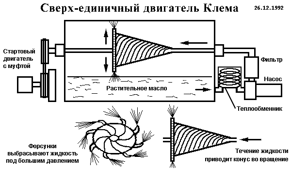
Жидкость подается в центральную ось под давлением 300-500 фунтов на квадратный дюйм, проходит по спиральным каналам и выпрыскивается через форсунки, что заставляет конус вращаться. Чем больше давление жидкости, тем быстрее вращается конус.
При дальнейшем увеличении скорости жидкость нагревается, что требует наличия теплообменника и фильтра. При некоторой скорости конус начинает самостоятельное вращение, независимое от двигателя. Скорость вращения вала достигает 1800-2300 оборотов в минуту.
Как только у изобретателя случился сердечный приступ и его документы были изъяты, его сын отвез один действующий двигатель на ферму неподалеку от Далласа. Там он залил его бетоном на глубине 10 футов, и двигатель продолжал работать на этой глубине в течение нескольких лет.
Из дальнейшего разговора следовало, что мотор был проверен корпорацией Bendix. Тест заключался в присоединении двигателя к динамометру для измерения мощности на валу.
Измерения показали, что двигатель устойчиво производил 350 лошадиных сил в течение 9 дней, что поразило инженеров фирмы Bendix. Они пришли к выводу, что источник, который может вырабатывать столько энергии в закрытой системе в течение столь длительного времени, может быть только ядерным.
Конструкция двигателя не содержит нетрадиционных деталей, за исключением конуса со спиральными каналами и пустотелого вала.
Ричард Клем работал в области тяжелого машиностроения в одном из пригородов Далласа. Он заметил, что определенные типы мощных насосов продолжали работать некоторое время после того, как отключалось питание.
Его любопытство по поводу этого явления привело к изобретению двигателя.
Вырезка из газеты: Сверх-единичный мотор Клема
В 1972 году Ричард Клем объявил об изобретении автомобильного двигателя, работающего на растительном масле.
Он продолжает настаивать на этом по сей день, несмотря на то, что его первый прототип мотора сломался и он обошел как минимум 15 компаний, прежде чем нашел финансовую поддержку.
48-летний Клем, оператор тяжелых машин в городе Далласа на пол-ставки, говорит, что если бы автомобилестроение взяло его изобретение на вооружение, водителям пришлось бы только менять 8 галлонов (30 литров) растительного масла на каждые 150 тысяч миль пробега и никогда не покупать бензин.
Клем говорит, что использовал растительное масло, потому что его двигатель работает при температуре 150 С, при которой вода выкипает, а обычное моторное масло разрушается. Хотя он и не хотел бы разглашать детали устройства двигателя, его единственным дополнительным источником энергии является 12-вольтовая батарея.
Когда Клем соорудил первый масляный двигатель в 1972 году, он предпринял пробное путешествие длиной в 600 миль до Эль-Пасо на моторе, который он сделал на свою зарплату. Перед тем, как все валы и все прочее погнулось, ему удалось доехать только до Абилина.
Он объяснил неудачу несовершенством конструкции, слишком маленьким размером вала и использованием цепей вместо шестеренок. Не унывая, он решил попробовать снова, но сказал, что ему нужны деньги, чтобы сделать эту вещь лучше.
Ни автомобильная промышленность, ни 15 других компаний, куда он писал, - даже в Тайвань - не были заинтересованы в финансировании и изготовлении его двигателя.
В последний год, как он сказал, одна угольная компания предложила ему помощь. Клем отказался назвать имя спонсора, но сообщил, что компания подписала контракт на продажу двигателей энергетическим компаниям в качестве тяговых турбин. Клем предполагает закончить работу над мотором к концу этого года (1972).
Примечание группы Авангард
Сообщается, что эта статья появилась в Флауэр-Маунде, штат Техас (к северо-западу от Далласа, недалеко от Кэролтона). Мне удалось дозвониться только до Клемов, которых я нашел в телефонной книге выпуска 20.11.92, но они не знают других Клемов в этом районе и не слышали о Ричарде Клеме и его родственниках.
Два визита в патентное бюро Далласской библиотеки оказались безуспешными - не было найдено никаких патентов Ричарда Клема на двигатели.
Мы продолжаем искать информацию об этом.
26.12.92 я нарисовал эту картинку, помогающую понять конструкцию машины, по крайней мере так, как она была описана нам.
Тем, кто занимается этой тематикой, сразу бросается в глаза связь с принципами Теории сопротивления пограничного слоя, касающимися многих работ Тесла. Мы обратили внимание на некоторые странности в поведении вращающихся масс с определенными скоростями. Скорость, при которой проявляется феномен, зависит от резонансной частоты данной массы как целого, как и указывал Кили.
Система Клема построена из традиционных компонентов. Самая сложная часть установки - конус. Исходя из Теории пограничного слоя, можно обойтись без конуса. Главный вопрос, связанный с двигателем Клема звучит так: "Обязательно ли нужен конус с расширяющейся поверхностью, дающий увеличение скорости вращения благодаря избыточному давлению, возникающему вследствие действия центробежных сил, или этого эффекта можно достичь с помощью плоских пластин, как в турбине Тесла?".
Мы продолжаем собирать информацию об этом устройстве и с благодарностью примем ваши комментарии и дополнительный материал.
Примечание АС.
Все выглядит довольно убедительно. Трудно разобраться, каково давление внутри оси, по которой подается масло. Жаль, что не указано, нагревается или охлаждается теплообменник. Я думаю, что должен охлаждаться, потому что другого источника энергии вроде бы не найти, кроме как теплота окружающей среды.
По всей видимости, жидкость внутри конуса становится перегретой, то есть на грани закипания. При выходе из форсунки она закипает, так как давление понижается. Энергия пара сообщает конусу дополнительный момент.
Это не просто кипение, а мгновенный взрыв перегретой жидкости, поэтому производится избыточная энергия. Это существенный момент, без которого получится традиционный паровой двигатель. Вместо масла можно применить любую жидкость с удобной температурой кипения, например, воду или пропан.
The Richard Clem Motor and the Conical Pump KeelyNet 03/21/02
An Investigation of the Clem Motor by Robert Koontz
In December of 1992 Jerry Decker posted an article on the KeelyNet BBS, about a self-running motor that developed excess useable power. The information, gathered from newspaper and individual sources, gave an anecdotal account of the motor invented in 1972 by Richard Clem of Flower Mound, Texas. New information has since been added and can be found on Keelynet.com at CLEM1.HTM.
Richard Clem worked with heavy machinery for the city of Dallas. He used asphalt-spraying equipment, which pumped liquid asphalt. He noticed the asphalt pump would continue to run for up to 30 minutes after the power was turned off. It was this discovery that led to the development of the motor. Modifications he made eventually resulted in a substantial 350 horsepower output from a 200-pound motor. Clem is said to have often driven a car, powered by this motor, up and down Central Expressway in Dallas. He claimed it didn't use any fuel, and only needed a change of oil every 150,000 miles.
The motor had only one moving part, a cone shaped rotor mounted vertically on a hollow shaft. Spiral channels cut into the cone wound around its length and feed into peripheral nozzles at its large end. When fluid flowed through the spiral channels it was ejected out the nozzles and caused the cone to spin. At a certain velocity, the rotating cone became independent of the starter pump and began to operate by itself. At an operating speed of 1800 to 2300 RPM the fluid heated up to 300° F, requiring a heat exchanger. Vegetable oil was used because at 300° F water boils and conventional engine oil breaks down. A 12-volt battery was the only other power source.
Clem never applied for a patent because his motor design was derived from the asphalt pump that was already patented. Fifteen companies turned him down before a large coal company offered to back him and signed contracts to sell the motor. Soon after the deal was signed, Richard Clem died of a heart attack
The above account contains only what I considered to be relevant for analysis of the Clem motor. Visit http://www.keelynet.com/ for the original material.
The gear pumps, typically used for asphalt spaying, do not match the description of the pump used by the city of Dallas back in 1972. There should be public records showing what equipment manufacture the asphalt sprayer was purchased from. Since the asphalt pump was patented, I searched for a pump patent that met the following criteria:
- Patent issued on or before 1972
- Delivered pressure equivalent to a positive displacement gear pump.
- Cone shaped rotor with spiral channels.
- Self-propelling action.
- Capable of pumping a viscous fluid like asphalt.
- Large heat transfer to pumped fluids.
The following illustration is from US Patent 3,697,190 "Truncated Conical Drag Pump". The patent was issued October 10, 1972 (criteria 1) and appears to match the description of the asphalt pump that Clem converted into his motor.
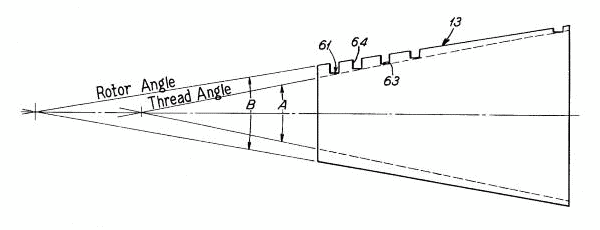
Housing 11, Conical interior wall 12, Conical rotor 13, Inlet chamber 14, Inlet pipe 15, Outlet chamber 16, Outlet pipe 17, Support feet 19, Detachable end cap 20, Rotor shaft 21, End cap wall 22, Boss 23, Packing 24, Adjustable gland nut 25, Bracket arms 27, Bearing boss 29, Bearing 30, Snap ring 31, Inner race 32, Sleeve 33, Shoulder 34, Retainer nut 35, Reduced diameter outer end 36, Coupling 37, Packing 39, Retainer 40, Gland nut 41, Bearing boss 43, Integrally formed bracket 44, Shaft reduced diameter 45, Bearing sleeve 46, Bearing 47, Snap ring 48, Inner flanged 49, Inner race 50, Nut 51,Shaft reduced diameter 53, Lock nut 55, Flat faces 56, Snap ring 57, Washer 59, Nut 60, Helical channel 61, Channel base 63, Channel sidewalls 64
This is a high-pressure, low volume drag pump that can be used in place of conventional positive displacement pumps (criteria 2). It has a conical rotor that has a close fit clearance with the stationary housing wall. Delivered pressure is limited by back flow across the radial clearance and is inversely proportional to the square of the clearance. As a result, even a small increase in radial clearance would rapidly reduce pressure. The rotor is cone shaped so that the clearance can be controlled by axial adjustment of the rotor relative to the housing wall.
The conical rotor has two helical channels (criteria 3), in the form of square threads, spaced 180° apart for balance. The channel depth decreases as the rotor diameter increases. Fluid enters the channels at the small end of the rotor. The fluid is induced to rotate with the channel by boundary layer drag. The boundary layer is the thin layer of fluid adhering to the channel surface. Molecular cohesion tends to drag the adjacent fluid with the boundary layer. The fluid is also in contact with the housing wall. The boundary layer drag against this stationary wall slows the rotation of the fluid in the channels. Because the fluid rotates slower than the rotor, it’s forced through the channels towards the large end of the rotor. In addition the fluid is forced towards the large end by centrifugal force.
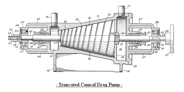
The above drawing illustrates the proportional decrease in channel depth as the rotor diameter increases. Why was this done? Note that as the diameter doubles so does the circumference. This means the fluid has to travel twice as far in the same time to maintain a constant slip velocity. By reducing the channel depth in half (cross-section area = depth x width) the fluid velocity is doubled thereby keeping the slip constant.
The spiral channels could be thought of as very long convergent nozzles. The increase in fluid velocity is in the opposite direction of the rotor spin. We should expect a reaction force from the acceleration of the fluid. This thrust would be directed tangent to the circumference and would increase the spin torque on the rotor. Even without the peripheral nozzles, that Clem later added, the pump rotor experiences a thrust force in a direction that would self-propel it (criteria 4).
Because fluid drag is the primary pumping force, it is well suited for viscous fluids like asphalt (criteria 5). The long channels also represent a large sliding surface area with frictional losses that would transfer heat to the pumped fluid (criteria 6).
All six of the patent search criteria have now been met. Of course this doesn’t prove that it is the asphalt pump Richard Clem worked with.
A peculiar condition indicated by the patent is that as the velocity increases in the channels the pressure also increases. Bernoulli’s Law requires the pressure to drop proportionally as the velocity increases. Assuming an ideal fluid without losses, when the channel depth is reduced in half, the cross section area is also half and this doubles the fluid velocity and the fluid pressure should drop in half. So what is going on here? There is a centrifugal component that would add to the fluid pressure.
My guess is it’s too small to overcome the predicted pressure drop. Here is what I think may be going on. As the diameter and velocity increases the drag force propelling the fluid through the channel is proportionally greater. Energy is being added all along the length of the channel. Whatever the reason, if this high-velocity, high-pressure fluid is feed into tangent peripheral nozzles at the rotor large end, the energy will be converted to shaft horsepower.
The Clem motor is producing 350 shaft-horsepower and a large heat energy component. Where is this huge amount of energy coming from? Resent quantum mechanics zero-point field (ZPF) theories may point to the answer. From an article available at
"Our work suggests inertia is a property arising out of the vast, all-pervasive electromagnetic field we mentioned earlier, which is called the zero-point field (ZPF). The name comes from the fact that the field is held to exist in a vacuum-what is commonly thought of as "empty" space-even at the temperature of absolute zero, at which all thermal radiation is absent."
ZPF researchers theorize that mass, inertia and gravity are not intrinsic properties of matter but the interaction of matter with the zero-point field. By "all pervasive" is meant that the ZPF exists not only in "empty space" but it is passing through your body right now and everywhere else. When you throw a stone you are interacting with this field since the ZPF resists change in motion. In essence the ZPF is the modern day aether.
The amount of energy making up the ZPF is thought to be enormous. Is the fluid acceleration in the Clem motor interacting with the ZPF in such a way as to rectify it and draw energy from it? Is it a hydraulic aether-diode? The fluid, in the Conical Drag Pump, flows through long convergent channels. Disregarding the boundary layer, is this accelerated flow laminar? Would such a long orderly flow entrain the aether energy?
From the perspective of the rotating channels the fluid appears as the discharge from a long nozzle. To exaggerate, if the fluid was held fast to the housing wall, the rotating channel would travel through the stationary fluid. This would be equivalent to achieving 100% efficiency. In reality the fluid is slipping against the stationary housing wall so that the rotating channel ("nozzle") is moving faster than the fluid discharge velocity. Assuming the reaction thrust as the only propelling force, this would give efficiency greater than 100%. So, as the slip increases the reaction thrust decreases, but the efficiency increases.
Assuming the Conical Drag Pump is the pump Clem used, can it answer the following?
- Why was a hollow shaft used?
- Why was the cone mounted vertically?
- Why was a starter pump needed?
- How were the peripheral nozzles added?
- How was the motor RPM regulated?
- How did a large coal company get involved?
- Was this kind of pump ever used in asphalt sprayers?
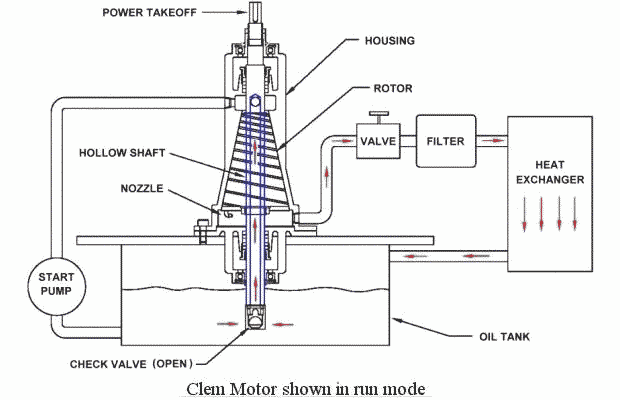
Red arrows show oil flow
The above drawing shows a hypothetical Clem motor based on the Conical Drag Pump. The motor is mounted vertically so that the check valve on the hollow shaft is submerged down in the oil tank. The hollow shaft (shown in blue) extends from the oil tank through the rotor into the inlet chamber. The start pump draws oil from the tank and forces it up the external feed line connected to the inlet chamber at the small end of the rotor. This fills the hollow shaft and forces the check valve closed. The oil flows into the spiral channels and out the peripheral nozzles. The reaction thrust of the nozzles spins the rotor. The oil flows through the return line, through the valve, filter, and heat exchanger and back into the tank. The start pump is most likely a standard hydraulic gear pump. It continues to pump until the rotor spins up to its operating speed. The combinations of a start pump and check valve would be a simple way to both prime the motor and spin up the rotor.
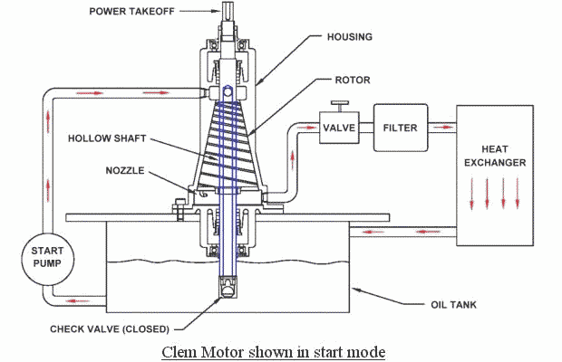
Red arrows show oil flow
Once the start pump is shut off the check valve is free to open. Oil is drawn up into the hollow shaft (shown in blue) to the inlet chamber at the small end of the rotor. The spiral channels pump the oil down towards the large end of the rotor. A plate is attached to the large end of the rotor and fits with a close clearance with the housing wall. Nozzles attached to the outer edge receive high-pressure oil from the spiral channels. The jet reaction thrust from the nozzles delivers shaft horsepower to the power takeoff at the shaft top. Adjusting the valve to create hydraulic backpressure regulates the motor RPM. Closing the valve stops the motor.
When I first read about the Clem Motor I found it odd that a deal had been made with a coal company. Was there a connection with the pump? After finding the Conical Drag Pump patent, I wanted to contact the inventor Walter D. Haentjens of Barrett, Haentjens & Co., Hazleton, Pennsylvania. Otto Haentjens founded Barrett Haentjens & Co., in 1916. The business began in the coalmines of Pennsylvania with Otto Haentjens original patent on the balanced opposed impeller multi-stage volute pump. The company still supplies pumps to the coal industry. They have expanded to other markets and their pumps are installed in many industries worldwide. It’s now known as Hazleton Pumps Inc., after its acquisition by The Weir Group.
I contacted Peter Haentjens, the VP/General Manager of Hazleton Pumps, by e-mail to find out if this pump had ever been put into production. He replied that they had not done anything with the patent.
E-mail sent 11/18/2001
To: Peter Haentjens, VP/General Manager Hazleton Pumps
Hi Peter,
I’m interested in a pump developed by Barrett Haentjens & Co. (now Hazleton Pumps Inc.?). During a patent search I found a 1972 patent (3,697,190) for a "Truncated Conical Drag Pump" invented by Walter D. Haentjens of Sugarloaf, PA. The attached image is the front page from this patent. Did your company ever manufacture this pump? If so, is it still available?
I appreciated any information you can provide.
Thanks
Robert Koontz
E-mail received 01/19/2002
From: Peter Haentjens, VP/General Manager Hazleton Pumps
Dear Robert,
Sorry for the late reply to your email. We have not done anything with this patent. I would be interested to know the nature and extent of your interest in this design.
Peter
An unusual pump design would have a tough time competing in the market with an industry standard like gear pumps. The Dallas asphalt sprayer may have been a one of a kind field test of the pump design. Or the pump manufacturer offered it for testing to an asphalt equipment company in the hopes of generating interest in it.
Robert Koontz - Original Clem Cone file
Slavek Krepelka - Clem File